

Almost every Arduino journey starts with one small green light. There is a good reason the Blink sketch is the universal first program: most boards carry a built-in LED wired to digital pin 13, so you can upload code and watch something happen without touching a single jumper wire. Get that working, then add a sensor, and you have learned both output and input in one sitting.
Quick Answer
Upload the Blink example to your Arduino and the on-board LED on pin 13 flashes with no external wiring needed, usually running in under two minutes. Once it blinks, wire in a push-button or PIR sensor and you have moved from controlling an output to reading an input.
Step 1: Blink the built-in LED
Plug your Arduino Uno into your PC with a USB cable and open the Arduino IDE. Go to File, then Examples, then Basics, and choose Blink. The sketch is already written for you.
Select your board and the correct port under the Tools menu, then click Upload. After a few seconds the LED near pin 13 starts flashing on and off at one-second intervals. That single result confirms your board, cable, drivers and IDE are all talking to each other, which is the real point of the exercise.
Step 2: Read the Blink code
The sketch has two parts. The setup function runs once and sets pin 13 as an output. The loop function runs forever: it turns the pin on, waits a second, turns it off, waits another second, and repeats.
Change one number to prove you understand it. Lower the delay value from 1000 to 200 and re-upload. The LED now blinks five times faster. Editing one value and seeing the result is the fastest way to grasp how the code maps to behaviour.
Step 3: Add a push-button as your first input
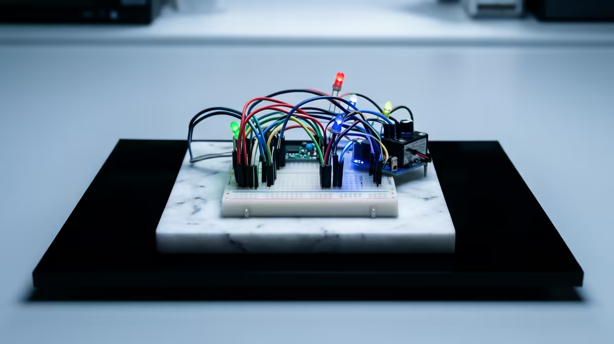
Now you teach the board to listen. Wire a push-button to a digital input pin with a resistor, or use the internal pull-up so you need fewer parts. In the sketch, read the pin's state and switch the LED on only while the button is held.
This is the conceptual leap from Step 1. Blink told the Arduino what to do; the button lets the Arduino react to the world. That input-then-output pattern underlies almost every project you will build later.
Step 4: Swap in a PIR motion sensor
Once a button works, a PIR motion module behaves the same way in code: it outputs high when it detects movement. Wire its signal pin to a digital input and light the LED whenever motion is sensed.
Suddenly you have a tiny motion alarm. From here the path opens up to temperature sensors, light sensors and relays, and you can browse smart home and sensor modules to pick your next component. The breadboards, jumper wires and resistors that hold it all together sit among the project accessories worth keeping in your kit.
What the Arduino IDE is Actually Doing
Understanding the tool helps you debug faster. When you click Upload, the IDE compiles your C code into machine instructions the microcontroller understands, then sends the compiled program to the board over the USB serial connection. The board's bootloader receives it and stores it in flash memory. After the upload completes, the program starts running immediately and will restart each time the board powers up.
If the IDE cannot find your board, the most common cause is the wrong port selected in the Tools menu. On Windows, check Device Manager for a COM port that appears when the Arduino is plugged in, then match that port in the IDE. On a Mac, the port shows up as something like /dev/cu.usbmodem followed by numbers.
Useful Wiring Habits to Build Early
A few habits from the first project pay off on every project after it. Always connect power and ground before signal wires. Use resistors with LEDs from the first build, even the built-in LED already has one on the board. Label your breadboard columns with a marker so you can trace a circuit quickly when something misbehaves. Never change wiring while the board is powered if you can help it, because a short circuit during wiring is the most common cause of early frustration.
A small note on the Uno specifically: pin 13 has a built-in resistor on the board, which is why the Blink example does not need an external one. Any other pin driving an external LED does need a resistor, typically 220 to 470 ohms for a standard 5V red LED. That distinction is worth learning early.
Frequently Asked Questions
Why is Blink the first Arduino program?
Most boards have an LED already wired to pin 13, so Blink runs with no external components. It proves your whole toolchain works before you add any complexity.
Do I need extra parts for the first step?
No. The on-board LED means the Blink sketch runs straight after upload using only your Arduino and a USB cable.
How do I make the LED blink faster?
Lower the number inside the delay calls. Changing 1000 to 200, for example, makes each on and off phase last a fifth of a second.
What sensor should a beginner add first?
A push-button is the simplest input to learn the read-then-act pattern. A PIR motion sensor is a great next step because it outputs a clean high or low signal just like a button.
Can I use any Arduino board for this?
Yes. The Uno is the classic choice, but the Blink example and the input-then-output approach work across the common Arduino boards with only minor pin differences.
Ready to build your first circuit? Grab the sensors and electronics modules at Evetech and go from a blinking LED to a working project this week.