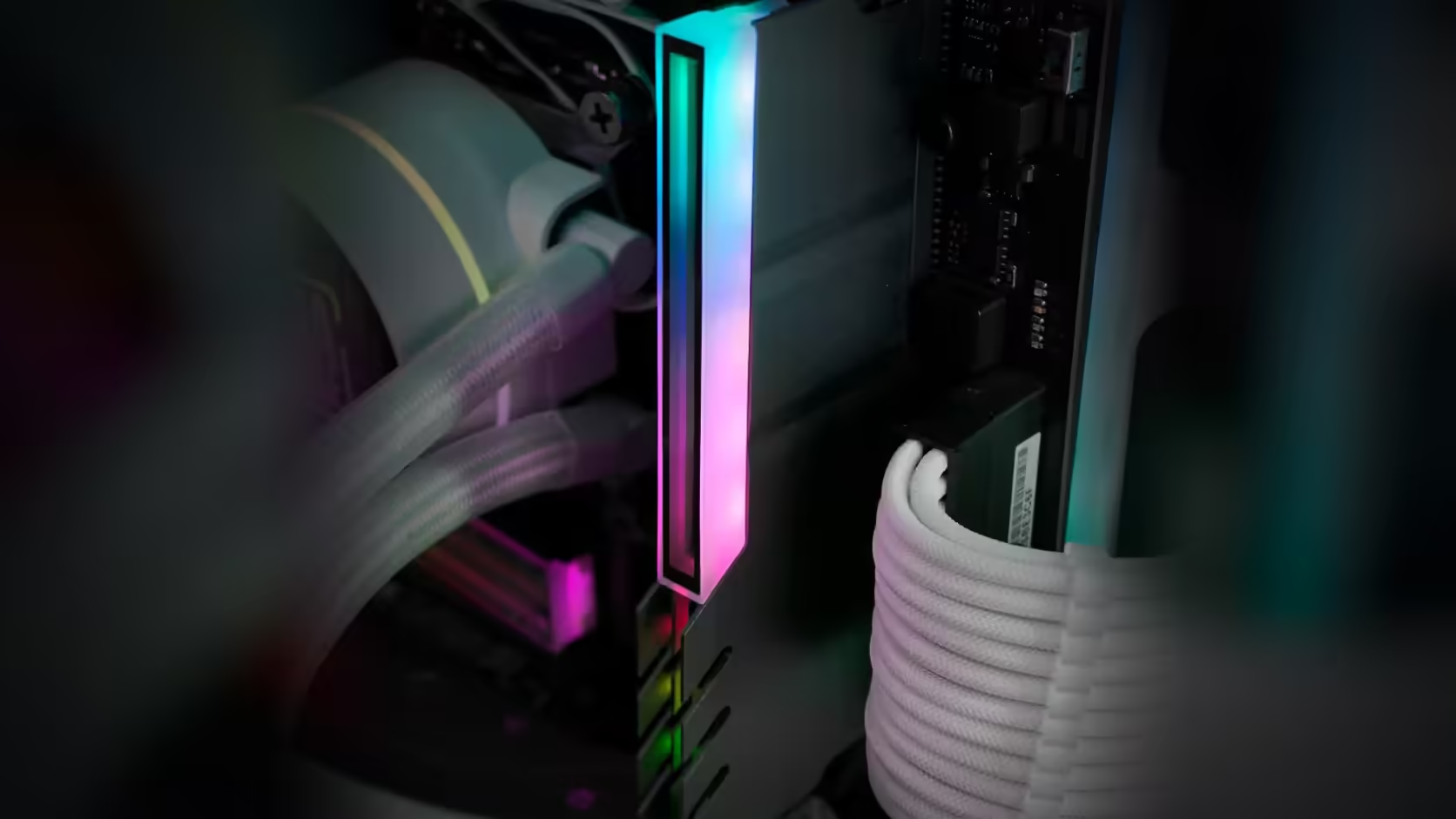
Every memory slot has a release clip that has to be reached to pull the module free, and it is easy to forget those clips exist right up until the day you actually need one. Fitting a RAM cover adds a lighting lead into exactly that area, and routing it badly turns a five-second job into an unplugging exercise first.
Quick Answer
Away from the release clips at either end of the DIMM slot - that is where the lighting lead from an AsiaHorse RAM Cover ARGB Heatsink, R249 with VAT included, needs to run, along the top of the module instead. Those clips need to be pressed to free a stick for removal, and a lead draped across them turns a routine memory swap into extra disassembly first.
🔓 Where the clips actually are
Depending on the board, release clips sit at one or both ends of every populated slot, and pressing them is what allows a module to lift free. Some boards use a fixed end and a single working latch, which halves the exposed area but does not remove the problem entirely - one clip left blocked is still a blocked clip.
🧵 A route that keeps them clear
Running the lead along the top of the modules toward the nearest case edge, then down to the header, generally keeps both clip ends untouched. Leaving a little slack in the run means a module can be lifted slightly during memory work without the lead pulling taut, which matters more than it sounds once you are actually mid-repair with the board still mounted.
When several covers are fitted together
A single cover is a simple routing job. Several covers across a populated row mean several leads converging toward one header, and a planned route along the row - rather than each lead finding its own path - keeps the whole area tidier and avoids one lead crossing another directly over a clip.
🔗 Using the chaining to your advantage
The lead's male and female ends exist precisely so covers can link to each other along a row, which keeps the wiring to one run reaching the board rather than several separate leads criss-crossing the slot area. Light cable ties along that single run help, provided they are placed loosely enough not to pull the leads tight across the slots themselves.
Whether you are working with DDR5 memory or DDR4 memory, the clip positions and routing principle are the same - it is the board's layout that decides where the clips sit, not the memory generation.
🧪 Test the route before it is permanent
Before tidying any lead down with ties, do a dry run: reach for the release clip on the module you have just fitted the cover to and confirm the lead does not have to be moved out of the way first. This takes seconds and catches a bad route while it is still trivial to change, rather than after the whole row has been dressed and tied down. A route that looks fine by eye can still sit close enough to a clip that a finger pressing it also catches the lead, which is exactly the kind of thing that only shows up when you actually try the motion rather than just looking at it.
🗂️ Board manuals sometimes show clip positions
Some motherboard manuals include a diagram of the memory area showing exactly where each slot's clips sit, particularly on boards marketed with heavier VRM or cooling shrouds nearby. Checking that diagram before routing anything, where one exists, saves a certain amount of guesswork - though in its absence, a visual check of the installed board with the case open works just as well.
🔄 Revisiting the route after any change
Adding or removing a module later is exactly the moment a previously good route can stop being one - a new cover changes what the row looks like, and a lead that cleared cleanly before may now cross differently once the arrangement shifts. Treat any change to the populated slots as a reason to glance over the routing again, rather than assuming the original plan still holds once the board layout has changed underneath it.
Frequently Asked Questions
Where are the release clips?
At one or both ends of each memory slot, depending on the board, and they have to be pressed to free a module.
Why does the lead interfere?
Because it leaves the cover near the top of the module, so a careless route drops it straight across the clip area.
Where should it go instead?
Along the top of the modules towards the nearest edge, then down to the header, keeping the clip ends clear.
Does slack help?
Some slack allows a module to be lifted slightly without the lead pulling, which is useful during any memory work.
What if several covers are fitted?
Then several leads converge, so a planned route along the row matters more than with a single cover.
Should the leads be tied?
Light ties keep them tidy, provided they do not pull the leads tight across the slots.
Planning a full row of lit covers and want the wiring done right?
Browse Evetech's DDR4 and DDR5 memory range while you plan the lead routing before you install anything.